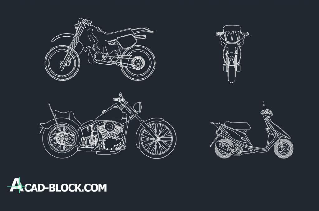
Znak Severa Dwg
CE mark Vector. Choose from thousands of free vectors, clip art designs, icons, and illustrations created by artists worldwide!
A light planning program for calculation and visualization of indoor and outdoor lighting systems. DIALux can import from and export to all CAD programs (DXF, DWG, SAT.) and has photorealistic visualization with an integrated ray tracer. More than 66 free electronic catalogues and photometric files (IES, EULUMDAT, CIBSE.) can be read in.
It is available in 25 languages. DIALux is undergoing continuous refinement. The latest standards are always taken into consideration as well as planning regulations and customs of the specific country. DIALux can calculate daylight, interior and exterior lighting, road lighting and emergency lighting. It includes an easy to handle DIALux Light for simple projects and the possibility to create movies directly from the lighting design. Screen Shots • Tool website URL(s).
Question: The option “Check dimension Point Validity” is not available in the Tekla version 2018. Please advise how to activate this command. Answer: We have enhanced the command Associativity symbol in TS 17.0 & later, At that same time, the commands Check Dimension point validity & Remove Dimension point invalidity Symbol removed from TS version 18.0, both commands are no longer available. Check Dimension point validity not showing the associativity symbol for the newly creating dimensions if you did not click the same every time. In the new Associativity symbol (Shift+A.
Question: In my model, few points are showing in blue colour & rest of the points are showing in red colour. I am working in TS2018. I observed that the same construction point which shown in blue colour in one view is showing as red colour in another view. What is the reason of this colour change for the same point in differnet views? Answer: In TS2018, You will get the point colour as blue if you are placing your point in plane and you will get the point colour as red if you are placing your point, out to plane.
Because of the above reason, points are appearing in different. Question: How to search many connections in new Applications and Components (version 21.1 onwards)?
In previous versions, we can get the same by searching the connection numbers by typing the connection numbers with space, for an example 141 17 (141 space 17) Answer: You can achieve your requirement by typing the connection numbers with “OR” in the search option among the connection numbers. For an example, type 141 OR 17 OR 144 (141 space OR space 17 space OR space 144)Note: You can use “or” otherwise “OR” during the search. Question: How to transfer the Plate profiles from Tekla Structures to Smart3d by using the Export to Smart3D link? For an example, PL32*250 Answer: You need to map RS* profiles of Smart3D with PL* profiles of Tekla Structures. For an example, You need to map the plate profile in “External name” as “RS32X250” in “Specify mappings “ in the “Export to SP3D link” dialog box during export if your plate profile is PL32*250 in “Tekla Structures Name” Note: You should have RS32X250 in your Smart3d profile catalogue.
Click “Save Changes for Next Time” in the “Export to SP3D link” if you want. Art dabbler 21 update download. Question How to export black and white pdf drawings and only cloud marks in Red? Answer Set color of cloud which is not used in the drawing for any other object. In below case Magenta color is used for cloud.

Then go to Print Drawings command and set Color option as color, see below. Then go to Line properties tab and change output color for all colors as black except color of cloud (Magenta) To change particular output color just click it and then you can select other color. Then output of the pdf drawing will come as below.
Same thing can be used for cloud and comments. Question: I have modelled a beam with shear studs. I'd like to copy them across to another beam but it is at a different elevation and plane, is this possible? Answer: Yes, the Copy special > To another object command is perfect for this and the advantage is you don't need to know the distance or level you are copying to, as it copies object to object. The objects that you copy between must be similar but can have different dimensions, length, and rotation. Let's explore it a little more, in the first example we will copy some shear studs from one beam to another beam of a different size. Question: I'm currently working on a project where a large portion of the formwork is repeated several times, do you have any advice to help speed up the modelling process? Answer: Formwork layouts can now be mirrored and copy rotated.