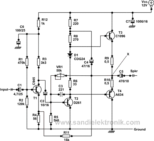
Skema Rangkaian Driver Power Amplifier
Upstream b2 workbook. This is HIGH POWER AMPLIFIER circuit diagram by using CLass D Power Amplifier System using a Mosfet for Final Transistor Amplifier. See the circuit. Download fnet turbohdd usb serial key generator.
The stereo signals coming from the line outputs of the car radio amplifier are mixed at the input and, after the Level Control, the signal enters the buffer IC1A and can be phase reversed by means of SW1. This control can be useful to allow the subwoofer to be in phase with the loudspeakers of the existing car radio. Then, a 12dB/octave variable frequency Low Pass filter built around IC1B, Q1 and related components follows, allowing to adjust precisely the low pass frequency from 70 to 150Hz. Q2, R17 and C9 form a simple dc voltage stabilizer for the input and filter circuitry, useful to avoid positive rail interaction from the power amplifier to low level sections.